Designer:
Craig J. Coley
Project Category:
Bookshelf Speakers
Project Level:
Beginner
Project Time:
1-8 Hours
Project Cost:
$100 – $500
Project Description:
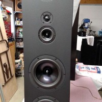
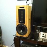
This project is the Coley A6 speaker. It combines a Dayton reference woofer and large area Dayton AMT with a somewhat unorthodox crossover to provide full range performance in a very modest enclosure. The idea was to make a small full range speaker with presence and detail of an electrostatic with enough bass that a subwoofer was not necessary for most music types. These speakers are paired with the Coley W225 tube amplifier and are my primary speakers.
Design Goals:
The origins of the Coley A6 began with design and construction of an electrostatic speaker for jazz music, my primary listening genre. The detail and articulation of an electrostatic is ideal but it came at the price of complexity, high operating voltage, environmental instability and very low impedance at high frequency. Air Motion Transformers (AMT) offer the same advantages of low moving mass and good articulation without the complexities of electrostatic. While many AMT drivers are relatively small and have crossover points above most of the midrange, the Dayton AMTPRO-4 has a comparatively large emitting area and convenient crossover frequency. The amplifier loading of the A6 speaker is somewhat variable but it only drops below 8 ohms below 100Hz; at high frequencies where amplifier stability can be a problem, the impedance is above 8 ohms and largely resistive.
Driver Selection:
Dayton RS180-4
Dayton AMTPRO-4
Enclosure Design:
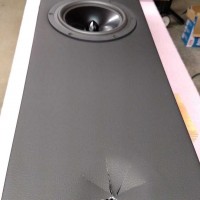
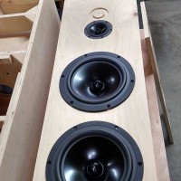
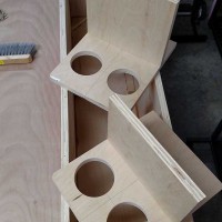
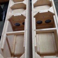
Space for the speakers was limited so they were designed to be no taller than necessary to accommodate the drivers and 6” deep shelf-type port. Solid cedar 1”x8” lumber was used for an overall cabinet size of 18”x7.5”x9”. Solid cedar was chosen instead of MDF because of the possibility of formaldehyde emissions causing problems with asthmatic children. Since these were developmental prototypes, there was also the desire to assemble the cabinet with screws to make internal changes easy. No degradation was noticed in the performance due to the use of screws but all holes had to be predrilled. More accomplished carpenters with access to routers or CNC equipment could make a superior cabinet from MDF; the materials and design were chosen due to unique needs and limited carpentry skills.
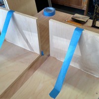
Enclosure Assembly:
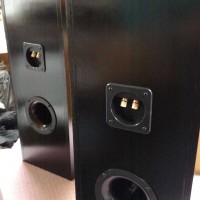
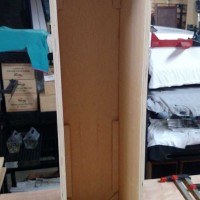
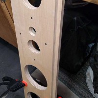
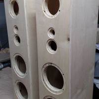
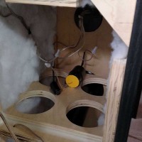
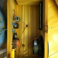
Once the lumber was cut, the box was hand-fitted and holes drilled to accommodate #6×1.5” wood screws. Predrilling is absolutely mandatory when using solid lumber because splitting along the grain is problematic. Once the enclosure sides are completely assembled, the entire enclosure was sanded with an orbital sander until all surfaces and joints were smooth. After sanding, hole-saws were used to create holes for the woofer and terminal block and a jig saw was used to create the rectangular hole for the AMTPRO-4 and port hole. The port shelf occupies the full width of the enclosure and stops 1” from the rear cover. The front panel port hole was intentionally varied between each speaker prototype to determine dimensional criticality. A 1”x4” port size was used on one speaker and 1”x5” on the other with no audible difference. A port hole smaller than 1”x4” was not tested and may cause chuffing.
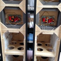
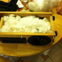
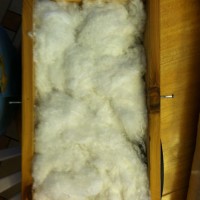
At this point, the cabinet was finished with two coats of natural tung oil. Once the tung oil had dried, the crossover components were mounted to the rear cover, the speakers wired and then finally mounted to the enclosure. #6×3/4 black sheet metal screws were used for speaker mounting to predrilled holes. Before installing the final side cover, the entire cabinet is loosely filled with 1 pound of Polyfill, fluffed as necessary to fill the cabinet volume. Polyfill serves to reduce the velocity of sound in the enclosure by around 20%, making the cabinet volume appear acoustically larger than its physical size.
Crossover Design:
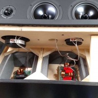
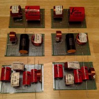
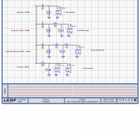
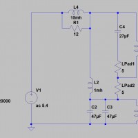
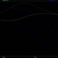
Since I personally like the sound and smooth transition of first order series crossovers, SPICE was used to model a series crossover design that takes into account the driver circuit characteristics. Fine tuning was still by ear but SPICE modeling was a great help getting very close to the final values. The 100uF capacitor connected across the Dayton RS180-4 is made by connecting two 47uF poly caps in parallel. All components were mounted to the rear panel which allowed easy removal during development.
Since the enclosure was relatively small, an additional L+R circuit was added to increase the available drive to the woofer below 100 Hz. The inductance of this circuit determines the transition frequency while the resistance value affects the depth. This L+R bass-boost circuit is fairly common with open-baffle designs and can be modified to tailor the enclosure used. Some driver efficiency is lost to boost the bass but even with a 25W amplifier, the performance is excellent.
Tips & Tricks:
To even someone with minimal carpentry experience, the Coley A6 should be easy to build with normal woodworking tools. If solid cedar is chosen and care is taken not to split the wood during assembly, the aesthetics are reasonable. The L-Pad and other fixed resistors specified in the design were chosen for use with a 25W amplifier; higher power systems will require higher wattage resistors. Also, bass-boost can be adjusted up or down by adjusting the 12.5 ohm resistor but higher values will reduce overall efficiency further.
Conclusion:
I had doubts about AMT performance versus an electrostatic when I started this project but the results have been beyond expectation. Getting good bass from a small enclosure was also a challenge but the A6 has more than enough bass for most usage except maybe hip-hop but that is not my listening preference.
About the Designer:
This project was designed and constructed by Craig J. Coley of Burleson, TX. I work as an electrical designer and am listed as inventor on 8 US patents in the field of electro-optics. I have been an electronics hobbyist since I built my first Heath radio at age 7 and a ham radio operator since age 11.
Project Parts List: